TDS Sensor
Reference : http://wiki.dfrobot.com/Gravity__Analog_TDS_Sensor___Meter_For_Arduino_SKU__SEN0244
TDS (Total Dissolved Solids) indicates that how many milligrams of soluble solids dissolved in one liter of water. In general, the higher the TDS value, the more soluble solids dissolved in water, and the less clean the water is. Therefore, the TDS value can be used as one of the references for reflecting the cleanliness of water.
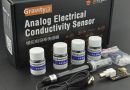
TDS pen is a widely used equipment to measure TDS value. The price is affordable, and it is easy to use, but it is not able to transmit data to the control system for online monitoring to do some water quality analysis. The professional instrument has high accuracy and can send data to the control system, but the price is expensive for the ordinary people. To this end, we have launched an analog TDS sensor kit which is compatible with Arduino, plug and play, easy to use. Matching with Arduino controller, you can build a TDS detector easily to measure the TDS value of liquid.
This product supports 3.3 ~ 5.5V wide voltage input, and 0 ~ 2.3V analog voltage output, which makes it compatible with 5V or 3.3V control system or board. The excitation source is AC signal, which can effectively prevent the probe from polarization and prolong the life of the probe, meanwhile, increase the stability of the output signal. The TDS probe is waterproof, it can be immersed in water for long time measurement.
This product can be used in water quality application, such as domestic water, hydroponics. With this product, you can easily DIY a TDS detector to reflect the cleanliness of water to protect your health.
| Attention: 1.The probe can not be used in water above 55 degrees centigrade. 2.The probe can not be left too close to the edge of the container, otherwise it will affect the reading. 3.The head and the cable of the probe are waterproof, but the connector and the signal transmitter board are not waterproof. Please be careful. |
|---|
Specification
- Signal Transmitter Board
- Input Voltage: 3.3 ~ 5.5V
- Output Voltage: 0 ~ 2.3V
- Working Current: 3 ~ 6mA
- TDS Measurement Range: 0 ~ 1000ppm
- TDS Measurement Accuracy: ± 10% F.S. (25 ℃)
- Module Size: 42 * 32mm
- Module Interface: PH2.0-3P
- Electrode Interface: XH2.54-2P
- TDS probe
- Number of Needle: 2
- Total Length: 83cm
- Connection Interface: XH2.54-2P
- Colour: Black
- Other: Waterproof Probe
Board Overview

| Num | Label | Description |
|---|---|---|
| 1 | – | Power GND(0V) |
| 2 | + | Power VCC(3.3 ~ 5.5V) |
| 3 | A | Analog Signal Output(0 ~ 2.3V) |
| 4 | TDS | TDS Probe Connector |
| 5 | LED | Power Indicator |
Basic Tutorial
This tutorial will show you how to measure the TDS value of the water. Please read this tutorial carefully, and pay attention to the steps and details.
| The probe can not to be used in water above 55 degrees centigrade. The probe can not be too close to the edge of the container, otherwise it will affect the reading. The head and the cable of the probe are waterproof, but the connector and the signal transmitter board are not waterproof.Please pay attention to use. |
|---|
Requirements
- Hardware
- DFRduino UNO R3 (or similar) x 1
- Analog TDS Sensor / Meter Module x 1
- TDS Probe x1
- Jumper Wires x3
- tested liquid x1
- Software
- Arduino IDE (Version requirements: V1.0.x or V1.8.x), Click to Download Arduino IDE from Arduino®
Connection Diagram

Advanced Tutorial
Through the basic tutorial, the TDS value of the liquid can be easily measured. However, due to the individual differences of the TDS probe, the difference of the main control board, and without temperature compensation, the measured value will cause a little big error.Therefore, to obtain a more accurate TDS value, calibration is required before measurement. In addition, it is recommended to connect a temperature sensor for temperature compensation to improve accuracy. Normally, the TDS value is half of the electrical conductivity value, that is: TDS = EC / 2. The wiring diagram is same as the basic tutorial. During the calibration, the liquid solution of known electrical conductivity or TDS value is needed, such as 1413us/cm standard buffer slution. If converted to a TDS value, it is about 707 ppm. The TDS value can also be measured using a TDS pen if you have not the standard buffer solution. The following will demonstrate how to calibrate.
Download and install the DFRobot Gravity TDS Sensor Library. How to install Libraries in Arduino IDE?
Sample Code
/***************************************************
 DFRobot Gravity: Analog TDS Sensor/Meter
 <https://www.dfrobot.com/wiki/index.php/Gravity:_Analog_TDS_Sensor_/_Meter_For_Arduino_SKU:_SEN0244>
 ***************************************************
 This sample code shows how to read the tds value and calibrate it with the standard buffer solution.
 707ppm(1413us/cm)@25^c standard buffer solution is recommended.
 Created 2018-1-3
 By Jason <jason.ling@dfrobot.com@dfrobot.com>
 GNU Lesser General Public License.
 See <http://www.gnu.org/licenses/> for details.
 All above must be included in any redistribution.
 ****************************************************/
 /***********Notice and Trouble shooting***************
 1. This code is tested on Arduino Uno with Arduino IDE 1.0.5 r2 and 1.8.2.
 2. Calibration CMD:
     enter -> enter the calibration mode
     cal:tds value -> calibrate with the known tds value(25^c). e.g.cal:707
     exit -> save the parameters and exit the calibration mode
 ****************************************************/
#include <EEPROM.h>
#include "GravityTDS.h"
#define TdsSensorPin A1
GravityTDS gravityTds;
float temperature = 25,tdsValue = 0;
void setup()
{
    Serial.begin(115200);
    gravityTds.setPin(TdsSensorPin);
    gravityTds.setAref(5.0);  //reference voltage on ADC, default 5.0V on Arduino UNO
    gravityTds.setAdcRange(1024);  //1024 for 10bit ADC;4096 for 12bit ADC
    gravityTds.begin();  //initialization
}
void loop()
{
    //temperature = readTemperature();  //add your temperature sensor and read it
    gravityTds.setTemperature(temperature);  // set the temperature and execute temperature compensation
    gravityTds.update();  //sample and calculate
    tdsValue = gravityTds.getTdsValue();  // then get the value
    Serial.print(tdsValue,0);
    Serial.println("ppm");
    delay(1000);
}
Calibration Step
- Uploaded the sample code to your controller board, then open the serial monitor.
- Clean the TDS probe, then dry it with the absorbent paper. Insert the probe into the buffer solution of known electrical conductivity or TDS value, then stir gently, waiting for stable readings. If you have not the standard buffer solution, a TDS pen can also measure the TDS value of the liquid solution.
- Input command “enter” to enter the calibration mode.

- Input command “cal:tds value” to calibrate the sensor.In this example, I use the 707ppm buffer solution, so I need to input command “cal:707”.

- Input command “exit” to save and exit.

- After the calibration, you can use the TDS sensor in your application now.
FAQ
| Q1. Does this sensor have a temperature sensor? How to make the temperature compensation? |
|---|
| A1. This TDS probe has no temperature sensor, but the temperature compensation algorithm is reserved in the sample code. The temperature variable in the sample code will default to 25 °C without a temperature sensor. You can add a waterproof temperature sensor to read the temperature,then update the temperature variable, to make automatic temperature compensation. |
| For any questions, advice or cool ideas to share, please visit the DFRobot Forum. |
|---|
More Documents
 Get Gravity: Analog TDS Sensor/Meter for Arduino from DFRobot Store or DFRobot Distributor.
Turn to the Top