EC Sensor V1 By DFROBOT
Introduction
- Want to DIY an EC meter? Need to measure the conductivity value? Find it difficult to use with Arduino? Don’t understand conductivity? Here comes an analog EC meter,specially designed for Arduino controllers and has built-in simple, convenient and practical connection and features. When done the connection according to the diagram, then with the program control, it’s very convenient to measure the conductivity value.
- Conductivity is the ability of substance to carry the current. It is the reciprocal of resistivity. In liquid, we often use the reciprocal of resistance, that is conductance, to measure the conductive capacity. The conductivity of water is a important indicator in the measurement of water quality. It can reflect the level of electrolytes present in the water. Depending on the concentration of the electrolyte, the conductivity of the aqueous solution is different.
- In the International System of Units, the uint of conductivity is Siemens / meter (S/m), and the other units are: S/m, mS/cm, μS/cm. Conversion relationship is: 1S/m = 1000mS/m = 1000000μS/m = 10mS/cm = 10000μS/cm.
Specification
- Operating Voltage: +5.00 V
- PCB Size: 45mm × 32mm
- Measuring Range: 1ms/cm~20ms/cm
- Operating Temperature: 5-40 ℃
- Accuracy: <±10% F.S (specific accuracy depends on the accuracy of your calibration solution)
- PH2.0 Interface (3-pin SMD)
- Conductivity Electrode (Electrode Constant K = 1, BNC connector)
- Cable Length of the Electrode: about 60cm
- DS18B20 Temperature Sensor (Waterproof)
- Power Indicator
Electrode Size

Use the EC Meter (Elementary)
Connecting Diagram

Step to Use the EC Meter
Cautions
- Please use an external stable power supply (such as 7.5V DC), and the voltage of MCU system as close as possible to the +5.00V. More accurate the voltage, higher the accuracy!
- Before measuring a different solution, you need to use water to wash the conductivity electrode and temperature sensor, in order to prevent contamination and inaccurate result. The deionized water is recommended to wash the electrode and sensor.
- When measuring the conductivity of the solution, make sure that the temperature sensor is inserted into the test solution first. You should use the conductivity electrode to stir the solution. This will let the conductive portion of the electrode have a full contact with the solution. When the temperature and conductivity value is stable, you can read the required value.
- Affected by the polarization, we will get some conductivity values jittered when we measure high conductivity solution. The higher the conductivity, the more powerful values jittered.
NOTE: Long-firing Operation: Sampling test method was used to test the EC value, dont support to immerse into solution for a long time, so please take out the electrode from solution after testing.
Life Span: In 25 ℃, pure water, PH 6-8, it can work about one year, and just for reference, if put it in turbid, strongly acid and alkali solution, 25℃, the life span would drop to half a year even less time. The life span depends on your using environment.
STEPS
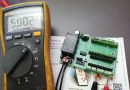
- Connect equipments according to the connecting diagram, that is, the conductivity electrode is connected to the BNC connector on the EC meter board, and then use the analog connection line, the EC meter board is connected to the anlong pin 1 of the Arduino controller. The temperature sensor is connected to the connecting terminal of the terminal sensor adapter. Then you should use the digital connection line, the terminal sensor adapter is connected to the digital pin2 of the Arduino controller. When the Arduino controller gets power,you will see the blue LED on board is on.
- Upload the sample code to the Arduino controller.

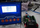
- Open the serial monitor of the Arduino IDE, you will see some information such as temperature, voltage, conductivity and so on. If you don’t put the electorde in the solution, you will see “No solution!”
- Put the conductivity electrode and temperature sensor into the calibration solution, stir the solution for some time and wait for the stable readings. If the conductivity reading on the serial monitor is close to the solution’s conductivity, you can apply it in your project now. e.g. The conductivity of the solution is 1413us/cm.

Sample Code
Firstly, please install the library OneWire.
// #
// # Editor     : YouYou from DFRobot
// # Date       : 23.04.2014
// # E-Mail : youyou.yu@dfrobot.com
// # Product name: Analog EC Meter
// # Product SKU : DFR0300
// # Version     : 1.0
// # Description:
// # Sample code for testing the EC meter and get the data feedback from the Arduino Serial Monitor.
// # Connection:
// #        EC meter output     -> Analog pin 1
// #        DS18B20 digital pin -> Digital pin 2
// #
#include <OneWire.h>
#define StartConvert 0
#define ReadTemperature 1
const byte numReadings = 20;     //the number of sample times
byte ECsensorPin = A1;  //EC Meter analog output,pin on analog 1
byte DS18B20_Pin = 2; //DS18B20 signal, pin on digital 2
unsigned int AnalogSampleInterval=25,printInterval=700,tempSampleInterval=850;  //analog sample interval;serial print interval;temperature sample interval
unsigned int readings[numReadings];      // the readings from the analog input
byte index = 0;                  // the index of the current reading
unsigned long AnalogValueTotal = 0;                  // the running total
unsigned int AnalogAverage = 0,averageVoltage=0;                // the average
unsigned long AnalogSampleTime,printTime,tempSampleTime;
float temperature,ECcurrent;
//Temperature chip i/o
OneWire ds(DS18B20_Pin);  // on digital pin 2
void setup() {
 // initialize serial communication with computer:
  Serial.begin(115200);
  // initialize all the readings to 0:
  for (byte thisReading = 0; thisReading < numReadings; thisReading++)
    readings[thisReading] = 0;
  TempProcess(StartConvert);   //let the DS18B20 start the convert
  AnalogSampleTime=millis();
  printTime=millis();
  tempSampleTime=millis();
}
void loop() {
  /*
   Every once in a while,sample the analog value and calculate the average.
  */
  if(millis()-AnalogSampleTime>=AnalogSampleInterval)
  {
    AnalogSampleTime=millis();
     // subtract the last reading:
    AnalogValueTotal = AnalogValueTotal - readings[index];
    // read from the sensor:
    readings[index] = analogRead(ECsensorPin);
    // add the reading to the total:
    AnalogValueTotal = AnalogValueTotal + readings[index];
    // advance to the next position in the array:
    index = index + 1;
    // if we're at the end of the array...
    if (index >= numReadings)
    // ...wrap around to the beginning:
    index = 0;
    // calculate the average:
    AnalogAverage = AnalogValueTotal / numReadings;
  }
  /*
   Every once in a while,MCU read the temperature from the DS18B20 and then let the DS18B20 start the convert.
   Attention:The interval between start the convert and read the temperature should be greater than 750 millisecond,or the temperature is not accurate!
  */
   if(millis()-tempSampleTime>=tempSampleInterval)
  {
    tempSampleTime=millis();
    temperature = TempProcess(ReadTemperature);  // read the current temperature from the  DS18B20
    TempProcess(StartConvert);                   //after the reading,start the convert for next reading
  }
   /*
   Every once in a while,print the information on the serial monitor.
  */
  if(millis()-printTime>=printInterval)
  {
    printTime=millis();
    averageVoltage=AnalogAverage*(float)5000/1024;
    Serial.print("Analog value:");
    Serial.print(AnalogAverage);   //analog average,from 0 to 1023
    Serial.print("    Voltage:");
    Serial.print(averageVoltage);  //millivolt average,from 0mv to 4995mV
    Serial.print("mV    ");
    Serial.print("temp:");
    Serial.print(temperature);    //current temperature
    Serial.print("^C     EC:");
    float TempCoefficient=1.0+0.0185*(temperature-25.0);    //temperature compensation formula: fFinalResult(25^C) = fFinalResult(current)/(1.0+0.0185*(fTP-25.0));
    float CoefficientVolatge=(float)averageVoltage/TempCoefficient;
    if(CoefficientVolatge<150)Serial.println("No solution!");   //25^C 1413us/cm<-->about 216mv  if the voltage(compensate)<150,that is <1ms/cm,out of the range
    else if(CoefficientVolatge>3300)Serial.println("Out of the range!");  //>20ms/cm,out of the range
    else
    {
      if(CoefficientVolatge<=448)ECcurrent=6.84*CoefficientVolatge-64.32;   //1ms/cm<EC<=3ms/cm
      else if(CoefficientVolatge<=1457)ECcurrent=6.98*CoefficientVolatge-127;  //3ms/cm<EC<=10ms/cm
      else ECcurrent=5.3*CoefficientVolatge+2278;                           //10ms/cm<EC<20ms/cm
      ECcurrent/=1000;    //convert us/cm to ms/cm
      Serial.print(ECcurrent,2);  //two decimal
      Serial.println("ms/cm");
    }
  }
}
/*
ch=0,let the DS18B20 start the convert;ch=1,MCU read the current temperature from the DS18B20.
*/
float TempProcess(bool ch)
{
  //returns the temperature from one DS18B20 in DEG Celsius
  static byte data[12];
  static byte addr[8];
  static float TemperatureSum;
  if(!ch){
          if ( !ds.search(addr)) {
              Serial.println("no more sensors on chain, reset search!");
              ds.reset_search();
              return 0;
          }
          if ( OneWire::crc8( addr, 7) != addr[7]) {
              Serial.println("CRC is not valid!");
              return 0;
          }
          if ( addr[0] != 0x10 && addr[0] != 0x28) {
              Serial.print("Device is not recognized!");
              return 0;
          }
          ds.reset();
          ds.select(addr);
          ds.write(0x44,1); // start conversion, with parasite power on at the end
  }
  else{
          byte present = ds.reset();
          ds.select(addr);
          ds.write(0xBE); // Read Scratchpad
          for (int i = 0; i < 9; i++) { // we need 9 bytes
            data[i] = ds.read();
          }
          ds.reset_search();
          byte MSB = data[1];
          byte LSB = data[0];
          float tempRead = ((MSB << 8) | LSB); //using two's compliment
          TemperatureSum = tempRead / 16;
    }
          return TemperatureSum;
}
Use the EC Meter (Advanced)
According to the above-mentioned steps, you can easily measure the conductivity between 1ms/cm to 20ms/cm. But the vessel constant of each electrode is different, so the accuracy is not very high. You need calibration. So the following will introduce the principle of measurement and scheme of calibration.
Principle of Measurement
Firstly, please open the schematic and find the chip U3B. It consists of the reverse scaled circuit. The transfer function is Vo=R10/R*Vi. R10 is a feedback resistance and it’s value is 820ohm according to the schematic. R is the resisitance when the electrode inserted in aqueous solution. It’s value is related to the conductivity of the aqueous solution. R10/R is called magnification. When the R is changed, the magnification is also changed, so the Vo changed.So Vo is related to R. On the right of the reverse scaled circuit, there is a absolute-value circuit. It’s transfer function is Vo=|vi|. Arduino samples the output of the absolute-value circuit to calculate conductivity. The following analyses the calibration principle. Definition of resistance: ρ is the resistivity; L is the length of the resistor element; A is the cross section of a resistor. For the conductivity electrode, L is the spacing between two conductive sheets, A is the area of the conductive sheet. Definition of conductivity:
 According to the above two equations, we can get this equation:
 1/R is called conduction G.L/A is called vessel constant Q. The transfer function of the measurement circuit is:
  R is the resistance of the electrode when inserted into aqueous solution. In conclusion, we can get this equation:
 Q is the vessel constant. It is a constant and different from each electrode. In the schematic, R10 is 820Ω.|Vin| is also a constant depend on the signal generating circuit. It’s value is about 200mV. So we can see, the conductivity is linear with the output voltage.
Scheme of Calibration

- Make your solution temperature be at 25℃
- Do the wiring according to the above connecting diagram
- Upload the sample code in the above section: Sample Code
- Insert the probes (the conductivity electrode and the temperature sensor) into the solution A, e.g. the sample EC solution, 1413 uS/cm, and open the Arduino Serial monitor, you will read a average voltage, take it as V1. So the two numbers (V1, 1.413) composed to the first point Ain the picture on the right: (X1, Y1) = (V1, 1.413)
- Take out the probes and clean it with pure water
- Then submerge them again into another sample EC solution, 12.88ms/cm. read another average Voltage as V2. Now you get another point Bin the above picture, namely: (X2, Y2) = (V2, 12.88)
- With the two points (x1, y1) and (x2, y2), you can draw out the line to describe the relationship between the analog reading and the EC. Reading: how to draw out the line
This is how the three equations were calculated out using different EC solutions inbetween 1ms/cm ~ 3ms/cm ~ 10ms/cm ~ 20ms/cm in the sample code
if(CoefficientVolatge<=448)ECcurrent=6.84*CoefficientVolatge-64.32;   //1ms/cm<EC<=3ms/cm
else if(CoefficientVolatge<=1457)ECcurrent=6.98*CoefficientVolatge-127;  //3ms/cm<EC<=10ms/cm
else ECcurrent=5.3*CoefficientVolatge+2278;                           //10ms/cm<EC<20ms/cm
NOTE: This is a video about EC Calibration And you can get its code on Github.
Precautions
- There are two kinds of conductivity electrode, shiny electrode and platinum black electrode.platinum-plated black aims to increase the effective area of the electrode sheet and relieve being polarized. So in the measurement of large conductivity solutions, using a platinum black electrode is more appropriate.
- Platinum black electrode substrate surface attached loose platinum black layer, so it should be avoid touching any object and only rinsed with deionized water. Otherwise you will damage the platinum black layer, resulting in inaccurate measurement.
- If you found the performance of a platinum black electrode has decayed, you can use the ethanol and deionized water to wash the platinum sheet. This is very important in high-accuracy measurement.
- Platinum black electrode substrate surface attached loose platinum black layer,so in the measurement of samples, it is possible to adsorbe sample composition. After using the electrode, you must be timely to rinse the electrode.
- If you lay conductivity electrodes aside for some time, or use it for a period of time, the cell constant may change.If the accuracy requirements for measuring is relatively high, it is recommend that you should periodicly calibrate the cell constant according to the user manual of the instrument.
FAQ
| Q&A | Some general Arduino Problems/FAQ/Tips |
|---|---|
| Q | Can you give me details of conductivity solutions? |
| A | There are two kinds of EC solution for the four bottles. They are 1413 uS/cm and 12.88ms/cm. |
For any questions/advice/cool ideas to share, please visit DFRobot Forum.
More Documents
 Get Gravity: Analog Electrical Conductivity Sensor from DFRobot Store or DFRobot Distributor.
Category: DFRobot > Sensors & Modules > Sensors > Liquid Sensors